Well, this was no mean feat in the end, but lots of preparation did help make it ultimately migrate with only 70 minutes of downtime.
Why I did this
My home network does include one hosted server, as well as an SDR radio receiver that anyone can log into from the Internet side. Some of the server services I access from the outside, and also share my public bookmarks on one of the services. I also run a Reticulum social network, using I2PD, from behind the firewall.
My Asus consumer router hit 10 years old, and it stopped getting security patches and updates in Dec 2024. I did just buy a brand-new Asus router that had VLAN support, but I quickly discovered it could not handle any inter-VLAN traffic rules.
So I retuned the Asus router to Amazon SA and bought a Protectli firewall appliance from Amazon US.
Why OPNsense?
Between the two above paragraphs was a lot of frantic research into what would support VLANs properly. I wanted to do VLANs so that I could separate my IoT devices from my user computers, from my guest devices, from my CCTV system and WiFi cameras, from my Victron solar system, etc. But I needed some devices to still talk one-way to other devices, etc. For this, I needed granular management of the inter-VLAN traffic rules.
I saw I could go cheap and quick with one MikroTik Wi-Fi router with proprietary software which has a steep learning curve (so the Reddit consensus says), or I could 4x more expensive and get 3 different devices with open source OPNsense software with a slightly less steep learning curve.
I actually spent a whole week learning pfSense which I installed on an Intel NUC. It worked quite well, but when comparing pfSense with OPNsense I decided to go the full open source route instead. Their GUI’s differ a bit, but their underlying principles are the same.
So, at the last minute before the Protectli device was delivered, I changed to OPNsense.
What did I do wrong?
On the device’s front, I did realise that I needed 802.1Q VLAN aware switches. I bought two TP-Link TL-SG108E switches. They do what is needed for the VLANs and have PoE as well.
I bought that Asus router that had no inter-VLAN traffic rules.
I realised I required a fully manageable switch for my core switch (I could do MAC VLANs with this too, or even DHCP, if I wanted). I bought a TP-Link 8-Port switch for my core switch, but quickly discovered that if I wanted to create a LAGG link (2x Ethernet ports for load balancing, more throughput, and failover) then I would be at least one port short. So, I returned that switch and ordered the 16-Port TL-SG2218 as a replacement. In my haste, I bought a perfectly good switch, but realised it does not have PoE (I’ll let that ride).
Just to explain why the LAGG interface: The firewall has 4 2.5 GHz Ethernet ports on it. One is dedicated to the WAN side, and typically one would be for LAN. But that LAN port connects to a switch with 8 or more devices, then two more switches. The problem is that the single LAN interface, between the core switch and the firewall, can be a bottleneck if you are streaming media. A LAGG interface is two or more physical interfaces tied together into a virtual LAGG interface. So your 2.5G Hz LAN port could become a 5 GHz LAGG interface. But you need to create the LAGG interface on teh firewall and core switch before you create all your VLANs, as the VLANs but have that LAGG interface as their parent interface.
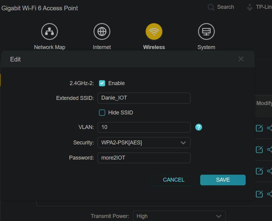
I was thinking I could use my older Wi-Fi router, or my newer Xiaomi router with OpenWRT installed, as the wireless AP. Well neither of those were to be, as they needed to have VLAN support too! So, I settled on buying the TP-Link TL-WA1801 wireless AP (TP-Link lingo is multi-SSID for when it supports VLAN tagging per wireless SSID). After starting to set that device up I saw no options for the VLANs and then thought, oh no, another mess up. But after reading the manual, I saw it defaults to AP mode, and you must change it to multi-SSID mode — solved! This allows me to set a specific VLAN for everything on the Guest network, another VLAN for the IoT network, etc.
Setting it up
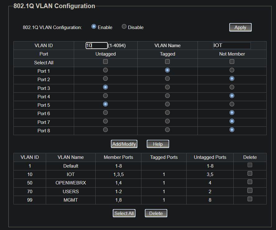
So, I spent the week after that refining my network diagrams as I added more VLANs. I cannot overestimate the IMPORTANCE of a detailed network diagram to show exactly what devices connect to which ports, which VLANs they must be in, and which are the trunk ports between the switches and the router. Because you need to have those ports connected to devices as untagged access ports, and the trunk ports set as tagged ports. I got this reversed on one switch, which meant none of its access devices appeared in their correct VLANs. They showed up as dynamic IP addresses in the MGMT VLAN.
The LAGG link also cost me days of going in circles. You either start with LAGG, or you don’t (because everything gets created off that LAGG link as the parent interface). It is way simpler to just have one network with everything in the 192.168.1.0/24 range. But when you have a LAN interface on one port, and a LAGG interface across two other ports, and everything has different address ranges, it gets very sticky.
Ultimately, what was getting me, was the end devices could obtain their VLAN IPs, but I could not see the actual management interfaces for the switches. I was doing all the setup using the LAN port on the firewall router. In the “very” end, I realised why many create a MGMT VLAN — you can have that also attached to the LAGG interface, and you can set static IP addresses for your switches and wireless AP to appear in that VLAN. You can also dedicate a port on the switch to the MGMT VLAN, so if you plug your laptop into that port, you see all the network devices that need to be managed.
But of course there was also a typo in the VLAN setup somewhere which was mysteriously resulting in some stuff not working. With pfSense and OPNsense for every VLAN you create, you have to:
* Create the VLAN
* Add it to the Interface
* Edit new Interface to set a static IPv4 address
* Create a DHCP service for it with an address pool
* Configure the firewall rules for it to see Internet or other VLANs
* Create the same VLANs on the switches
* Tag correct ports for each VLAN on the switches
* Create VLANs on the wireless AP
All the above have to synchronise, and you need to remember to also set each as active.
Going live
Only after I could see and manage my LAN switches could I go live. I still could not see the two switches that connected to my core switch, although the devices connected to them, were appearing in their correct VLANs.
Eventually I figured it must be because the switches themselves were not getting into the MGMT VLAN. Obviously, DHCP from the router was not working through to those switches. My core switch was appearing, and it was because I could set a secondary static IP address in the MGMT VLAN range. So I decided to take a chance and set one of my other switches to a static IP address in that same range. And there it appeared! Yes, there must be a way to have DHCP assign the address, but I had tried setting the switch’s port one to VLAN99 access, which locked me out of it. VLAN tagging is still something I need to understand a lot better!
So around 17:15 I decided to switch it on. Everything came on, and some devices were visible. Better than I expected! I had forgotten to add the IOT devices to be seen by the USERS VLAN. But there was zero Internet at all.
Lots of poking around the WAN side of things showed me that the static IP I had set was correct. I dug around for quite a while looking at logs until I saw something about the gateway. When I opened the gateway settings, I saw it was showing the first VLAN as its interface. I did an Internet search on OPNsense and gateway with static IP, only to find that OPNsense configures fine if you use DHCP for your WAN IP. So, it seemed I needed to set the gateway itself and make that the default then for the WAN interface.
After that, the firewall saw the Internet and got some updates etc. But none of my VLANs were seeing the Internet. I twiddled more with editing and resaving those gateway settings etc again, and eventually it all popped to life at around 18:29.
All that remained was the tweaking, like changing IPs from PC’s and phones to point to the media server’s new IP address. I had to change some settings in Home Assistant to point to the Victron system’s new IP address, lots of login IP address changes, etc.
I just had to update my Nginx Proxy Manager to also point incoming Internet traffic to the new IP addresses. One thing that puzzled me was why my OpenWebRx receiver was still not being seen from the Internet, yet I could access it by its LAN IP address. Eventually I saw the firewall rule pointed to the OpenWebRx address (which is actually the gateway address for the OpenWebRx VLAN, instead of the server itself). So, I edited that rule to rather point to an alias called OpenWebRxAdd (which was the address of the server itself). And OpenWebRx came to life as well.
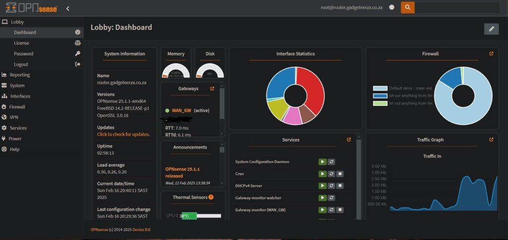
There is still lots of checking and tweaking to do, but all my main services are running fine. I am still quite amazed that it all came together at all.
Was it worth it?
Well it is early days still, but so far I’m extremely happy with it. All my devices have Internet access outwards except for the cameras, and all the other devices are isolated from each other outside of their own VLANs. I moved the Victron system onto its own VLAN in the end, as potentially it could disable the house if someone hacked it. The Home Assistant can only pull data from a specific Modbus port between the VLANs. My OpenWebRx SDR receiver on its Raspberry Pi is on its own isolated VLAN too. The USER VLAN for our PCs and phones are isolated from the MGMT VLAN.
I expect I’ll update this as I find some interesting aspects about managing the system later on. I do still have to enable the WireGuard remote access as well as the Intruder Detection and Prevention Systems.
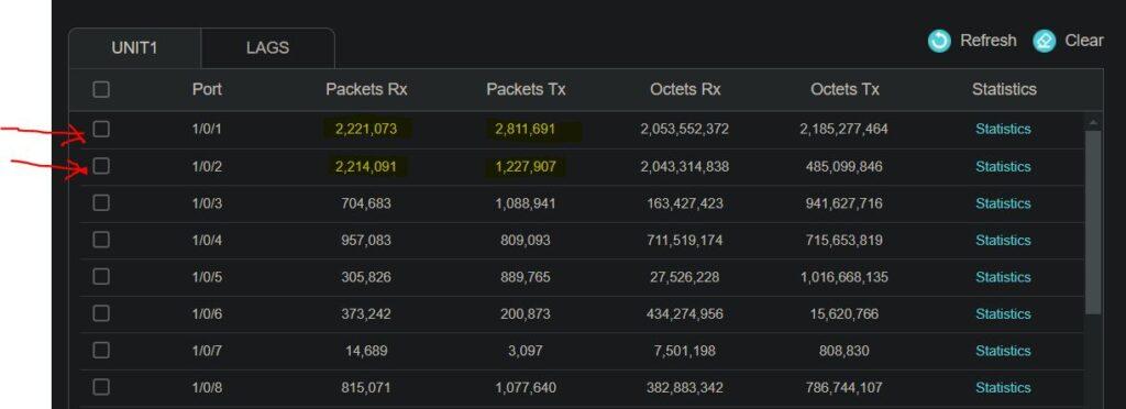
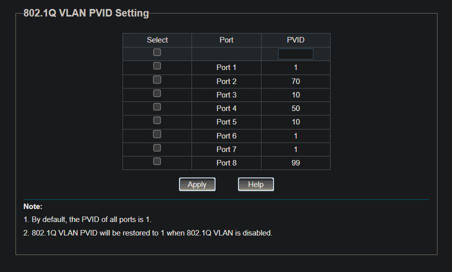
I’ll include a few screenshots below for reference as to what worked for the switch VLAN port settings.